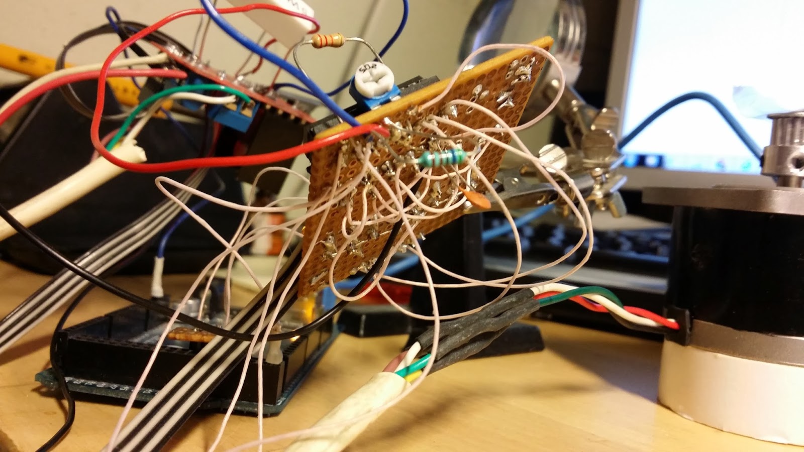
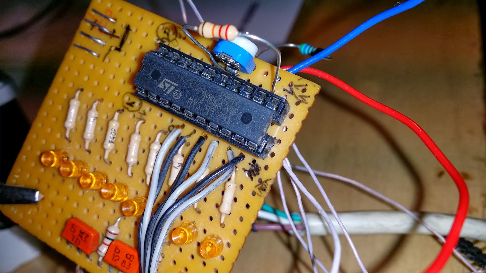
To begin with - I repaired my soldering iron but will order a new later. I builded a test version of stepper motor driver. Photos and video below.
It looks awful and complicated :)
I took a development board from the old project, where he was 20pin connector for chips and a bunch of LEDs
Board of power bridge had to slightly modify the. I cut two tracks on the board to connect the termination resistors (5W 1Ohm) to measure current consumption.
Work of embedded in L297 PWM generator
GIF. the first 4 LEDs connected to outputs of L297 and indicate the switching combination coils. 2 LEDs are connected to the ENABLE pins of L298, on which is the PWM signal for controlling the motor power.
The first video of the project on the YouTube :)
The next step - the development and production of printed circuit board.


No comments:
Post a Comment